NS-122-M-HA SISTEMA DE DISEÑO Y EVALUACIÓN PERSONALIZADO DE IMPRESIÓN 3D DE IMPLANTES BIO-MIMÉTICOS DE HUESO PARA INSTITUCIONES DE SALUD DE LA ZONA SUR DEL ESTADO DE MÉXICO
NS-122-M-HA SISTEMA DE DISEÑO Y EVALUACIÓN PERSONALIZADO DE IMPRESIÓN 3D DE IMPLANTES BIO-MIMÉTICOS DE HUESO PARA INSTITUCIONES DE SALUD DE LA ZONA SUR DEL ESTADO DE MÉXICO
Categoría: Superior (Licenciatura)
Área de participación: Mecatrónica
Resumen
Una de las desventajas al colocar dentro del cuerpo implantes fabricados de metales como el hierro, acero inoxidable y titanio, es que no tienen elasticidad ni densidad parecida al hueso humano. Además, por su tipo de superficie no siempre permiten la adecuada generación de tejido óseo, el cual se debilita con el paso del tiempo, hasta provocar que la pieza implantada salga de su lugar o inclusive se zafe provocando daños colaterales importantes. Bones Mirror pretende ser un servicio integral de diseño y manufactura avanzada de prótesis personalizadas de hueso, que tiene el fin de mejorar la calidad de vida de las personas que han padecido algún trauma grave o alguna enfermedad específica que impide que alguno de sus huesos se pueda regenerar de manera natural. La intención de este proyecto es realizar la prueba de concepto y las pruebas clínicas necesarias, para hacer llegar al médico ortopedista y a sus pacientes implantes óseos personalizados, que permitan regenerar hueso deforme, afectado por cáncer o traumatizado y recuperar casi en su totalidad su funcionalidad.
Pregunta de Investigación
¿Qué elementos de diseño se deben de considerar para generar un sistema personalizado de impresión 3D de implantes bio-miméticos de hueso para instituciones de salud de la zona sur del Estado de México?Planteamiento del Problema
La ingeniería de tejidos óseos en general y en particular el desarrollo de implantes porosos para regeneración de hueso por impresión 3D está siendo intensamente estudiada por la comunidad científica internacional.
A pesar de que el tema de reingeniería e impresión en 3D ha tomado mucha fuerza y de que se han encontrado múltiples aplicaciones de estos procesos, en Tejupilco, municipio del Estado de México, ubicado al sur con colindancia con los estados de Guerrero y Michoacán, no se ha realizado una aplicación más especializada a este tipo de desarrollos. Generar una reingeniería de hueso, de tal forma que permita generar estrategias de trabajo para el traumatólogo, mejorar los tiempos de operación y diseñar la prueba de concepto y los estudios clínicos necesarios, para poner en funcionamiento un sistema informático integrado de diseño y producción personalizada de implantes bio-miméticos de hueso, fabricados con biomateriales avanzados por impresión 3D, para la rehabilitación natural de huesos, no se ha desarrollado, y mucho menos aplicado en la zona.
Antecedentes
El hueso, el componente central del sistema músculo-esquelético, es un tejido conectivo duro, calcificado, que tiene como funciones proteger órganos vitales, proveer soporte para la movilidad del cuerpo, almacenar calcio y otros iones, al igual que células madres mesenquimáticas y hematopoyéticas (Buckwalter et al., 1996).
Si bien es cierto que los huesos humanos tienen ciertas propiedades auto-regenerativas, existen condiciones en las cuales estas propiedades no son suficientes para lograr la restauración del tejido dañado. Tal es el caso de la disminución de actividad celular endógena debido a tratamientos químicos para combatir el cáncer. Pero quizás la condición más común sea la ocurrencia de fracturas de gran tamaño, en donde el cuerpo no tiene la capacidad de seguir los procesos de reparación normales vía osificación endocondral y crea lo que se denomina fractura de no unión (Álvarez Barreto, 2009).
El hueso es hoy en día uno de los tejidos más trasplantados. Los injertos de hueso por fractura, presentan una incidencia anual de 15 millones de casos. (Gómez et al., 2016). La primera terapia empleada para reparar estas lesiones hasta ahora han sido las prótesis de materiales inertes (titanio y cementos óseos), que restablecen la función mecánica. Sin embargo, conllevan una serie de efectos secundarios que limitan su efectividad. El grado de interacción entre los materiales implantados y el tejido circundante es mínimo y provoca daño al tejido aledaño.
La impresión 3D es una tecnología que está revolucionando el campo de la medicina y, como no podía ser de otra forma, tanto la Cirugía Ortopédica como la Traumatología no son ajenas a este progreso (Fadero & Shah, 2014). En este contexto, el Emergency Care Research Institute situó a la impresión 3D en el segundo puesto de las 10 tecnologías de mayor impacto sanitario (Emergency Care Research, 2015) y la Food and Drug Administration de Estados Unidos ha publicado recomendaciones técnicas para su traslación clínica (Department of Health and Human Services. Food and Drug Administration., 2016).
La reconstrucción 3D de estructuras anatómicas a partir de imágenes médicas como Resonancia magnética (RM) y Tomografía axial computarizada (TAC), se ha convertido una herramienta importante en el diagnóstico médico y la planeación de terapias y procedimientos quirúrgicos. El procesamiento de imágenes médicas ha hecho posible el estudio biomecánico de estructuras óseas por el método de elementos finitos como herramienta para el análisis de geometrías y condiciones de contorno complejas (Isaza & Correa, 2008).
Los avances en reconstrucción tridimensional de las imágenes radiológicas han permitido disponer de herramientas virtuales para la planificación quirúrgica, pero es la impresión 3D la que posibilita la traslación de una planificación virtual a modelos tangibles (Huotilainen, et al., 2014). Existen muchos tipos de impresión 3D, aunque son las aditivas, y especialmente el modelado por deposición fundida de material termoplástico (FDM: fused deposition modeling) el que está teniendo mejor acogida en el sector empresarial y doméstico. Se han publicado revisiones de los métodos necesarios para su introducción en este campo, así como ejemplos de las primeras aplicaciones y usos específicos (Chen, et al., 2016)
Diversos estudios, como el realizado por la Dra. Palomar en el año 2015, en donde propuso una reconstrucción 3D de miembro inferior, a partir de una resonancia magnética, en donde esta situación permitió mejorar en las técnicas quirúrgicas y se pudo obtener una simulación, lo más cercana, al comportamiento biomédico del miembro (Jordán-Palomar & Rey-Vasalo, 2015). De la misma forma para Fromme, en donde asegura que cuando son niños y/o adolescentes los que sufren traumas en los huesos, los injertos óseos elaborados con metales debe ser sustituidos una o más veces, porque tienen altas tasas de aflojamiento, ya que el implante presenta un tamaño cada vez más pequeño en relación al necesario, a medida que los pacientes crecen (Fromme, et al., 2017).
La impresión en 3D de modelos anatómicos, generar instrumental o ayudas quirúrgicas impresas a medida y adaptadas a situaciones específicas, o facilitar el entrenamiento de personal médico mediante reproducciones personalizadas abre un horizonte de posibilidades, ya que se puede proponer, fabricar, evaluar sus propias soluciones, y participar en líneas emergentes como la bioimpresión de tejidos y órganos o la manufactura de implantes a medida (Shaunak, et al., 2016)
Estas situaciones han llevado a la investigación de ingeniería de tejido óseo, como un diseño de biomateriales para la construcción de andamiajes que apoyen el crecimiento de células y tejidos. Se ha hecho un esfuerzo de investigación importante para diseñar estructuras sintéticas que tengan propiedades similares a las del tejido nativo como resistencia mecánica adecuada y porosidad suficiente para permitir la infiltración celular y la organización de tejidos.
El diseño de andamiajes para regeneración ósea, debe ser tridimensional, altamente poroso e interconectado para soportar el ataque celular y la proliferación. Los poros son necesarios en la formación de tejido de hueso, porque permiten la migración y proliferación de osteoblastos y células mesenquimales, así como la angiogénesis y la vascularización. Además, la superficie porosa mejora la interconexión mecánica entre el biomaterial del implante y el tejido natural de hueso circundante. (Chatzinikolaidou, et al., 2015). El tamaño mínimo de poro requerido es de 100 a 180 µm.
Los materiales usados para la fabricación de andamiajes para regeneración de hueso tienen que tener suficiente integridad estructural, que se asemeje a las propiedades mecánicas del tejido nativo, y debe ofrecer un micro-ambiente ideal y crítico para funcionar como una matriz extracelular artificial, en la cual, las células puedan adherirse, crecer y forman nuevos tejidos.
Algunos materiales que presentan propiedades mecánicas, químicas y biológicas ventajosas que aparecen como materiales promisorios para la construcción de andamiajes para reparación ósea son:
- 50 mol% 2-(dimethylamino) ethyl methacrylate (DMAEMA) (Chatzinikolaidou, et al., 2015).
- Hidroxipatita (Fromme, et al., 2017 Hou, et al., 2016; García-Garduño, 2006).
- Hidrogeles de gelatina (Echave, et al., 2017)
La impresión 3D de prótesis elaboradas con materiales metálicos inerte tolerados por el cuerpo como titanio y acero inoxidable, se han probado también para tratar pacientes con defectos óseos del cráneo y maxilofaciales (Hong et al., 2016). Las complicaciones a largo plazo originadas por el uso de estos metales inertes ha incentivado la búsqueda de mejores alternativas. El uso de metales de utilidad metabólica está abriendo nuevas oportunidades en el área clínica.
Si las prótesis de hueso se elaboran con sustancias metálicas que son bio-absorbidas, los pacientes pueden evitar cirugías de eliminación en una etapa posterior (Hong et al., 2016).
El Mg es el metal más popular y atractivo de elección porque tiene propiedades muy similares a las del hueso y por eso es bio-absorbible. La única limitante es que se los andamiajes de Mg se degradan muy rápido. Para resolver este problema, se han investigado otras sustancias metálicas como el fierro que se degrada muy lentamente. La solución parece encontrarse en el empleo de aleaciones (Sealy, 2016).
En 2016, un grupo de investigadores de varios países publicaron los resultados de una combinación muy promisoria de Mg y Ca con Fe y Mn (Hong, et al., 2016). Estas sustancias fueron aglutinadas utilizando un procedimiento conocido como alta energía de aleación metálica (HEMA).
En el HEMA, los polvos de cada elemento se pulverizan juntos empleando bolas de acero inoxidable en un molino. Con este material puede construirse un andamio de cualquier forma capa por capa, a través de un proceso de impresión 3D, llamado aglutinante en chorro, en el cual se expulsa un aglutinante líquido a través de una boquilla, que mantiene la aleación en polvo unida. En un paso de curado posterior, se elimina al aglutinante de la estructura creada, mientras que el calentamiento subsecuente une a las partículas de polvo de la aleación (Hong et al., 2016; Sealy, 2016).
Se ha probado que la adición de Mg y Ca, puede acelerar la degradación del andamiaje y que la aleación de Fe Mn Mg y Ca es cito-compatible y la degradación del andamiaje puede ocurrir sin que se desencadene una respuesta tóxica. Para que una aleación resulte útil para la fabricación de andamiajes de hueso degradables, debe tener una combinación correcta de resistencia, ductilidad y degradación rápida controlada.
El único problema es que las partículas de aleación producidas por molienda tienden a variar en tamaño y forma. Esto puede producir estructuras bastante porosas, lo cual es bueno desde el punto de vista de la degradación, pero es menos ventajoso en términos de fuerza de compresión (Sealy, 2016). La fabricación inteligente de estructuras tridimensionales se ha vuelto muy importante en el área de ingeniería de tejidos de hueso.
La fabricación aditiva (AM) es una técnica de fabricación de capas sobre capa. En la mayoría de los casos, permite la fabricación de componentes complejos que son difíciles de fabricar o que no pueden fabricarse con métodos convencionales. Entre las prácticas de la AM, la impresión tridimensional en polvo (3DP) es la técnica más útil para las aplicaciones de ingeniería de huesos (Butscher A. et al., 2012; Zhou, Z. et al., 2014; Butscher, A., et al., 2011; Klammert, U. et al., 2010).
Las principales ventajas de la 3DP en polvo para la fabricación de andamiajes son su potencial de control máximo sobre la porosidad y su capacidad para reproducir el diseño anatómico personalizado con gran fidelidad a las imágenes anatómicas de 3D.
Las propiedades mecánicas y la permeabilidad son dos propiedades muy importantes de los andamiajes para regeneración ósea. Las propiedades mecánicas de estos andamiajes son altamente dependientes de los parámetros del proceso de impresión. El grosor de la capa, el tiempo de retraso entre la extensión de cada capa de polvo y la orientación de la impresión son los principales factores que determinan la porosidad y la resistencia a la compresión de un andamio impreso en 3D (Asadi-Eydivanda et al., 2016).
Se han desarrollado, muy recientemente, métodos matemáticos ligados tanto con el software de diseño asistido por computadora, como con la manufactura aditiva, que permiten la fabricación de estructuras para implantes que mimetizan las propiedades del tejido de hueso en todos sus niveles (microestructura, propiedades mecánicas, propiedades transporte de masa y propiedades biológicas), lo cual optimiza la penetración celular, la difusión de nutrientes y las propiedades de osteoconducción (Gómez et al., 2016; Zhongzhong et al., 2007).
La tomografía computarizada ha sido una herramienta muy utilizada para el desarrollo de modelos bio-miméticos que imitan la configuración interior del hueso natural y sirven de base para el diseño de andamiajes de nueva generación que son utilizados como implantes personalizados (Zhongzhong, et al., 2007).
Objetivo
General
Hacer la prueba de concepto y los estudios clínicos necesarios, para poner en funcionamiento un sistema informático integrado de diseño y producción personalizada de implantes bio-miméticos de hueso, fabricados con biomateriales avanzados por impresión 3D, para la rehabilitación natural de huesos.
Específicos
- Determinar el estado del arte, tendencias de innovación y la oferta tecnológica de prótesis personalizada para hueso.
- Probar y optimizar el sistema interfaz de comunicación entre las imágenes de la tomografía computarizada y el programa CAD de diseño de numérico del hueso.
- Probar y optimizar el programa de obtención imágenes tridimensionales especulares.
- Probar y optimizar el programa de diseño de implantes porosos bio-miméticos
- Probar y optimizar el sistema interfaz entre el diseño CAD de implante poroso bio-mimético y la impresora 3D.
- Establecer las variables críticas de impresión 3D para varios biomateriales candidatos.
Justificación
El presente trabajo busca generar una alternativa para disminuir largas cirugías de reconstrucción o anclajes de huesos, se presenta generar un diseño en 3D del problema real que sufre el hueso,al ser tomados por una TM o RX, al reconstruir, mediante el uso de software de diseño, el hueso a su forma real y en el tamaño del paciente, para que el cirujano pueda contar con más elementos de decisión, al mismo tiempo se diseñará la estrategia de andamiaje más adecuado a las condiciones del paciente para que el hueso pueda tener un sano crecimiento, de esta manera se evitará la compra de tornillos y placas así como el sufrir otra cirugía para su extracción, aplicándolas en hospitales públicos y privados de la zona sur del Estado de México.
Además se ofertará el trabajo de impresión 3D en plástico, para cirugías plásticas de reconstrucción, modificación o rediseño óseo, que permitan a los médicos contar con un modelo a tamaño, dimensión y lesión real para tomar la decisión más acertada, una vez aprobado el diseño se enviará a imprimir en la impresora de material biológico para posteriormente ser enviados a radiar para asegurar la inocuidad del implante.
Hipótesis
Con el diseño de las pruebas de concepto y los estudios clínicos necesarios, para poner en funcionamiento un sistema informático integrado de diseño y producción personalizada de implantes bio-miméticos de hueso, fabricados con biomateriales avanzados por impresión 3D, para la rehabilitación natural de huesos, se podrá dotar de estrategias al traumatólogo para asegurar los resultados de una operación, reducir los costos de compra de materiales metálicos y simplificar el proceso de cirugía, ya que la regeneración del hueso se dará de forma natural, disminuyendo el tiempo de recuperación y mejorando la recuperación de movilidad la parte afectada.
Método (materiales y procedimiento)
El estudio se llevará a cabo dentro de las instalaciones de la Universidad Tecnológica del Sur del Estado de México, situado en la parte sur del Estado de México, en el Municipio de Tejupilco San Miguel Ixtapan, Km. 12 Carretera Tejupilco – Amatepec). Tejupilco (en náhuatl “Texopilco”) es uno de los 125 municipios pertenecientes al Estado de México
Cuenta con una población de 71,077 habitantes según el censo de población y vivienda 2010. Su clima varía de cálido a húmedo y a semi-cálido húmedo con lluvias en verano y con un porcentaje menor de lluvias en invierno. Varían al igual que el máximo es de 40° en verano. Como primer punto en el desarrollo de este proyecto, se realizará una encuesta para conocer el grado de conocimiento y aceptación que el proyecto tendría en la región, se muestra en el anexo 1, esto permitirá diseñar las mejores estrategias de venta, una vez que ya se cuente con el desarrollo del sistema.
El proceso integrado de diseño y manufactura avanzada de andamiajes tridimensionales bio-miméticos para la generación de implantes personalizados de hueso, comprende nueve actividades secuenciales y seis programas matemáticos avanzados:
- Realización de una tomografía computarizada del hueso gemelo, sano. Las imágenes tomográficas, se apilan digitalmente para formar una imagen tridimensional. Programa 1. Modelaje de imágenes tomográficas
- La imagen tridimensional del hueso sano se convierte en una imagen tridimensional especular, que tiene la forma del hueso blanco antes de sufrir el daño. Programa 2. Programa interfaz escáner-CAD
- Usando como base la imagen tridimensional del hueso blanco,se diseña junto con el médico ortopedista un modelo tridimensional del implante. Programa 3. Diseño de implantes.
- El modelo del implante se modifica, para que tenga una estructura porosa similar a las trabéculas de hueso. Programa 4. Generación de implantes bio-miméticos.
- El modelo tridimensional numérico es convertido a un formato estéreo-litográfico (STL). y es transmitido a la máquina de impresión 3D en polvo.
- Un programa de software analiza el archivo STL y transforma matemáticamente el modelo de implante en secciones transversales con el espesor de capa seleccionado. Programa 5. Seccionado transversal del implante.
- Impresión 3D. Las secciones transversales se recrean depositando los biomateriales en polvo y un aglutinante líquido que es inyectado en chorros a través de una boquilla. Este proceso se repite capa por capa hasta que se forma un objeto 3D similar al modelo del implante. Después de la aplicación consecutiva de capas, se elimina el polvo remanente y así se obtiene el implante poroso terminado. Programa 6. Programa de impresión.
- El implante poroso terminado es empacado en una bolsa de plástico hermética y esterilizado con rayos gama en el Instituto Nacional de Investigaciones Nucleares.
- El implante poroso estéril se entrega en el hospital indicado, al médico ortopedista.
Bones Mirror funcionará bajo 6 programas matemáticos:
- Programa 1. Modelaje de imágenes tomográficas. Las imágenes tomográficas, se apilan digitalmente para formar una imagen tridimensional.
- Programa 2. Programa interfaz escáner-CAD. Convierte la imagen tridimensional del hueso sano en la imagen tridimensional del hueso blanco antes de sufrir el daño.
- Programa 3. Diseño de implantes. Puede modificar las imágenes tridimensionales de hueso para generar modelos tridimensionales que se adapten a las necesidades de los procesos quirúrgicos particulares.
- Programa 4. Generación de implantes bio-miméticos. Los modelos tridimensionales son modificados para que adquieran la estructura porosa deseada, similar a la que presentan las trabéculas de hueso naturales.
- Programa 5. Seccionado transversal del implante. Especifica los groses de capa necesarios para cada biomaterial.
- Programa 6. Programa de impresión 3D, que controla las variables del proceso de impresión en polvo.
El proceso de manufactura de andamiajes tridimensionales, como implantes bio-miméticos de hueso requiere una impresora 3D en polvo y los biomateriales avanzados, que se encuentran disponibles en el mercado:
- Hidroxiapatita de calcio
- Hidrogeles de gelatina
- Aleaciones de metales metabolizables: Fe, Mg, Mn y Ca
El diagrama de flujo de la Figura 1, muestra las actividades a desarrollar para poder brindar el servicio de impresión y manufactura personalizada de andamiajes tridimensionales bio-miméticos como implantes para la regeneración de hueso.

Figura 1. Proceso de impresión y manufactura de prótesis personalizadas (Huotilainen, Paloheimo, Paloheimo, Bjoskstrand, & Tuomi, 2014)
Galería Método

Resultados
Se aplicó la encuesta diseñada para poder conocer la aceptación del sistema personalizado de implantes biomiméticos de hueso, en donde se encuesto a aproximadamente 30 médicos de distintas instituciones tanto públicas como privadas, de la misma forma se encueto a personas que habían sufrido algún tipo de trauma en los huesos que requirió de una cirugía en donde colocaron clavos, tornillos, placas. Obteniendo los resultados más relevantes se presentan en las gráficas de las figuras 1 incisos (a) y (b), que a continuación se describen.


Figura 1. Gráficas de resultados
Fuente: autoría propia en excel
En la figura 1(a) se puede observar que el 50% de los encuestados estarían totalmente de acuerdo en trabajar con este desarrollo, mientras que el 17% menciona que las técnicas convencionales nunca dejarán de estar vigentes, los resultados son alentadores, ya que permiten continuar con el trabajo, esta nueva tecnología es aceptada por la mayoría de los cirujanos encuestados, argumentando que las personas estarían dispuestas a pagar por este tipo de servicios una vez conocidos sus beneficios.
Mientras que con respecto al trabajo en conjunto entre cirujano y médico para poder desarrollar este tipo de desarrollo, figura 1(b), se observa que sí están dispuestos al trabajo conjunto, ya que 50% contestaron totalmente de acuerdo y de acuerdo, a pesar de que algunos muestran resistencia al cambio, consideran que la impresión 3D puede resolver problemas mayores de una manera más simple, además de que se congratulan de que el trabajo ingeniería-ciencias de la salud resultaría en trabajos muy interesantes, por lo que no existe ningún inconveniente en iniciar trabajos conjuntos.
Una vez con los resultados obtenidos de la encuesta se procede a desarrollar la Metodología de impresión.
1.Tener tomografía computarizada (TAC) o resonancia magnética (RM) en formato DICOM
Para iniciar con el proceso se requería contar con una TAC o RM, al asistir a uno de los hospitales de la región, se consiguió iniciar trabajos en conjunto, y el primero fue autorizar al área de radiología para que se contará con una TAC, de 84 imágenes transversales, la cual fue tomada a un adulto de 27 años de edad, sexo masculino, el estudio fue tomado con un escáner Siemens Volume Zoom Multi-Slice CT System, Siemens®.
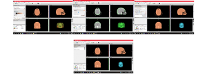
Figura 2. TAC de cráneo, paciente A
Fuente: Proporcionada por radiólogo

Figura 3. TAC de cráneo de paciente B
Fuente: proporcionada por radiólogo
2. Procesamiento y tratamiento de las imágenes médicas
Las imágenes del TAC se procesaron utilizando el programa invesalius3D, que es de acceso libre. En donde primero se cargó el estudio, posteriormente se determinaron las siguientes características entre las imágenes, ya que es importante hacer mención que se requiere de un proceso de reingeniería, en donde se debe de reconstruir la imagen, para posteriormente volverla un sólido que sea reconocido para poder generar su impresión. En donde la nube de puntos importada, se debe de procesar para poder generar el sólido correspondiente.
Los parámetros considerados fueron, distancia entre imágenes adyacentes igual a 1mm, posteriormente cada imagen fue segmentada utilizando un valor de umbral preasignado por el sistema, se genera un análisis de la imagen bajo el algoritmo de vecino próximo (vecindad de 8), en donde los pixeles específicos fueron marcados, en donde como se encuentran por encima del umbral asignado son convertidos a 1(valor blanco) y aquellos por debajo del umbral fueron convertidos a 0 (valor negro), es decir se realizó la binarización de la imagen, para poder seleccionar el área de interés. El software cuenta para este proceso con una barra de deslizamiento que permite ajustar los niveles de intensidad de grises de la imagen, según la estructura que se requiere reconstruir, para este ejemplo se reconstruyó una mandíbula, se manda a la opción de mallado, para este caso de estudio la nube generaba 32000 puntos, por lo que el proceso de mallada resultaba ser lento y en algunos casos no convergía, por lo que se redujeron a la mitas, es decir se trabajó con 16000 puntos para la generación de la malla.
Una vez hecho este proceso se guarda el mallado en formato STL para su posterior lectura y tratamiento. En la figura 4(a) se muestra el cráneo visto en el software 3DSlicer, posteriormente en la figura 4(b) se muestra la binarización y la generación de nubes de puntos para el área de interés.
(a) Cráneo en invesalius3D (b) Binarización y nube de puntos
Figura 4. Manipulación de TAC en 3 invesalius3D para generar nube de puntos del área de interés
Fuente: autoría propia en invesalius3D
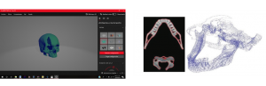
Se analiza también para comparar la eficiencia del análisis en autodesk fusión 360º, ya que se requería disminuir la nube de puntos para generar el mallado y no se generaran bucles infinitos, se puede observar en la figura 5.
Figura 5. Manipulación de imagen en Autodesk Fusion 360º
Fuente: autoría propia
Se pudo observar que los archivos STL no se pueden modificar primeramente en el programa de fusión 360º, así que se hace un proceso para reducir el mallado para que se pueda modificar en invesalius3D, ya que no es fácil la manipulación de archivos con extensión STL, ya que la cantidad de puntos de análisis es muy grande, por lo que primero se deberá de generar una optimización de puntos, de tal forma que no se pierdan características importantes del objeto a manipular.
Por lo que nuevamente con la nueva TAC se procedió a realizar el procedimiento de optimización, como se muestra en las figuras 6 y 7

Figura 6. Mallado de mandíbula.
Fuente: autoría propia

Figura 7. Nube de puntos optimizada
Fuente: autoría propia
3.Generación de superficies
Una vez con la nube de puntos, se manipula para generar el primer mallado, esto con la finalidad de identificar errores que se presentan al momento de la conversión, o para tapar y rediseñar aquellas superficies en donde se presente algún tipo de trauma, con este trabajo se asegura que el elemento que se entregue cumpla con las características para ser convertido en sólido, tales como superposiciones de capas, desviaciones angulares, paralelas mal consideradas, por mencionar algunos de los errores más recurrentes que se presentan al momento de generar reingeniería, ya que la calidad del producto dependerá del buen tratamiento en diseño que se realice. En la figura 8, se muestran dos de los errores que aparecieron al momento de analizar el mallado, y que debieron de ser reevaluados para que la mandíbula cumpla con las características mecánicas.

![]()
Figura 8. Errores marcados al momento de generar la malla
Fuente: autoría propia en invesalius3D
4.Generación de sólido
Una vez que se cuenta con la malla, se guarda en formato STL para ser importado a un software de CAD, que permita la manipulación del mallado para ser convertido en sólido y que pueda ser enviado a impresión, ya que si este proceso no se lleva a cabo la impresora 3D nunca podrá leer el proceso que se requiere, ya que no estaría imprimiendo a un sólido. En la figura 9 se muestra el tratamiento que se da al formato STL, que aunque parece en forma mesh, ya está convertido en un sólido, el cual puede ser enviado a impresión.

Figura 9. Mandíbula como sólido manejada en autodesk FUSION 360º
Fuente: autoría propia
Se está en estos momentos pasando a la parte de impresión, en donde hasta este momento solo se han impreso algunos huesos, a los que se les dio un tratamiento en cuento a nube de puntos y mallado pequeño, por lo que el resultado de impresión no es el que se esperaba, por lo que se están recalibrando los valores para poder pasar a la etapa de imprimir esta mandíbula y medir y observar el funcionamiento mecánico, para presentarla al médico y que sea evaluada en cuanto a eficacia y calidad del proceso, además de que se solicita una TAC de una fractura para poder generar el proceso de rediseño y presentar el andamiaje más correcto que sea personalizado, en la figura 10 se pueden observar el acercamiento que se tiene a estos trabajos, en donde se presenta un fémur en 3D ya convertido en sólido, su impresión y el primer acercamiento al andamiaje que se propone, ya que éste deberá de ser evaluado y poder determinar su funcionalidad.

Figura 10. Primeros trabajos de acercamiento a diseño de andamiaje e impresión 3D en filamento de PLA
Fuente: autoría propia
Con estos antecedentes y realizadas algunas pruebas se procedió a crear un andamiaje que se adapte de la mejor manera a la fractura que se tiene este procedimiento se tiene que llevar de la mano con un médico para que los modelos creados sean aceptados para colocar en el paciente, generando tres pruebas de concepto, según análisis realizado por el médico en seguimiento:
Prueba 1 de andamiaje
Se puede observar en las figura siguientes el desarrollo para el diseño de un andamiaje que permita unir de nuevo la fractura sufrida por el paciente, en donde de forma normal se colocaría una placa y tornillos para unirla


Figura 11. Muestra de la fractura e inicio del concepto andamiaje
Fuente: autoría propia
Una vez creado el andamiaje para la fractura se especifican los puntos de anclaje que se harán para que la mandíbula se sujete de la mejor manera, es importante hacer mención que en este caso se utilizarían tornillos desarrollados de un material absorbible por el hueso, de tal forma que no se tuviesen que retirar, como se observa en la figura 12.

Figura 12. Andamiaje desarrollado
Fuente: autoría propia
Después de que el médico realizó la primera evaluación del modelo,la prueba del andamiaje no obtuvo una buena evaluación. El andamiaje 1 fue rechazado ya que presentaba muchas irregularidades y no cumplía con los requerimientos para unir la fractura de la manera correcta y más eficiente.
Prueba de andamiaje 2
En la figura 13 se muestra la prueba para el andamiaje 2 propuesto, en donde ya se puede observar que unas partes se unirían con pegamento especial, mientras que solamente un punto de unión


Figura 13. Prueba de andamiaje 2
Fuente: autoría propia
El segundo modelo de andamiaje fue más acertado que el anterior ya que cumplía con las especificaciones para el tipo de fractura, aunque hay unos aspectos que se tienen que seguir resolviéndose como lo es el tamaño del andamiaje.
Prueba de andamiaje 4
En esta prueba se presenta un modelo de malla, con el que se espera poder colocarlo mediante pegamento óseo basado en hidroxipatita de calcio, el cual podrá ser maleable, en el sentido de que se podrá manipular de manera más simple en el miembro fracturado, no necesariamente la mandíbula, sino que se podría adaptar a otras partes óseas del cuerpo, esto se muestra en la figura 14.
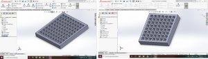
Figura 14. Prueba de andamiaje 3.
Fuente: autoría propia
Esta malla fue evaluada de manera exitosa, pero existe un problema a resolver, el médico solicita que se presente un medio que asegure de manera efectiva la sujeción al miembro óseo en tratamiento, por lo que se está, actualmente, en el desarrollo del elemento de sujeción que permita versatilidad operatoria.
A continuación se muestran algunas impresiones realizadas en plástico PLA, para poder presentar la mandíbula con el andamiaje propuesto, se puede observar en la figura 15.
 Custom prosthesis printing and manufacturing processCustom prosthesis printing and manufacturing process
Figura 15. Impresiones en PLA
Fuente: autoría propia
Galería Resultados


Discusión
El avance tecnológico en imagen médica, la posibilidad de obtención de mallas tridimensionales de localizaciones anatómicas concretas a partir de los estudios por lotes convencionales como la TAC o la RM, y la posibilidad de la impresión tridimensional implica un auténtico cambio de paradigma en la planificación y ejecución quirúrgica.
En localizaciones anatómicas complejas, como en el esqueleto axial, o en fracturas articulares en las que la reconstrucción de la superficie articular es crucial para el pronóstico de la lesión, que el profesional disponga de un modelo que reproduzca fielmente la anatomía de esta localización supone una herramienta visual y táctil, didáctica y eficaz.
Conclusiones
A pesar de las potenciales ventajas, se han identificado varios inconvenientes para la integración de la impresión 3D como herramienta dentro el proceso como es el desconocimiento de las posibilidades de transferencia de la tecnología existente por la falta de formación en nuevas tecnologías de los profesionales sanitarios implicados en el proceso.
Otro problema identificado es el exceso de oferta tecnológica para aplicaciones clínicas concretas, y no tanto para la práctica clínica habitual, y el costo de los programas de posprocesado de imagen para la obtención de la malla tridimensional y de las impresiones 3D de los modelos. No podemos olvidar la inexistencia de un marco regulatorio específico para la impresión 3D médica.
Una gran ventaja encontrada es que existen herramientas digitales gratuitas, programas de libre acceso que permiten generar acciones de procesado de la imagen, pero que en algunos casos limita el procesado por el número de puntos de la nube, además de que se deben de contar con conocimientos en ambas áreas de aplicación del conocimiento, ya que con la ayuda del especialista se pudo comprender la forma mecánica en la que actúan los elementos del cuerpo humano, principalmente la parte del sistema óseo.
Ya se ha avanzado en el proceso del procesado de las imágenes, ya se comprendió la diferencia entre un archivo en extensión DICOM y un STL, de la misma forma se comprendió la forma en que operan las impresoras 3D, ya que sea el material que se utilice como fundamento su principio es el mismo, y los archivos que se envían para su manejo deben de contar con la misma extensión, esta cualidad permite volver flexible el proceso, de tal forma que para el producto final se deberán de cumplir con especificaciones y regulaciones médicas para que el proceso sea implementado hasta el final.
Con los anclajes impresos, se presentaron ante el médico responsable, desechando uno de ellos, ya que no presentaba viabilidad, se generó un nuevo diseño, en el que se variaron los elementos recomendados.
Falta iniciar con el trabajo del análisis mecánico del comportamiento del anclaje, solamente que el tipo de materiales que se han utilizado no han permitido generar un modelo mecánico que permita realizar todo su análisis, ya que es muy quebradizo, por lo que se está modificando el material de impresión, aún cuando el costo se incrementó.
Bibliografía
Álvarez Barreto, José F. (2009). Regeneración ósea a través de la ingeniería de tejidos: una introducción. RET. Revista de Estudios Transdisciplinarios [en línea], 1 (Julio-Diciembre):[Fecha de consulta: 10 de junio de 2017] Disponible en:<http://www.redalyc.org/articulo.oa?id=179214945008> ISSN 1856-9161.
Asadi-Eydivanda, M., Solati-Hashjinb, M., Fathic, A., Padashic, M., Abu Osmana, N. (2016). Optimal design of a 3D-printed scaffold using intelligent evolutionary algorithms. Applied Soft Computing. Vol. 39 (2016) 36–47.
Buckwalter, J. A., Glimcher, M. J., Cooper, R. R., y Recker, R. (1996). Bone biology. I: Structure, blood supply, cells, matrix, and mineralization. Instr Course Lect, 45, 371-386.
Butscher A., et al., (2012). Printability of calcium phosphate powders for three-dimensional printing of tissue engineering scaffolds, Acta Biomater. 8 (1) (2012)373–385.
Butscher, A., et al., (2011). Structural and material approaches to bone tissue engineer-ing in powder-based three-dimensional printing, Acta Biomater. 7 (3) (2011)907–920.
Chatzinikolaidou M., Rekstyte, S., Danilevicius, P., Pontikoglou, C., Papadaki H., Farsari M., Vamvakaki, M. (2015). Adhesion and growth of human bone marrow mesenchymal stem cells on precise-geometry 3D organic–inorganic composite scaffolds for bone repair. Materials Science and Engineering C 48 (2015) 301–309.
Department of Health and Human Services. Food and Drug Administration., 2016. www.fda.gov. [En línea]
Available at: http://www.fda.gov/downloads/MedicalDevices/DeviceRegulationandGuidance/GuidanceDocuments/UCM499809.pdf
[Último acceso: 16 junio 2019].
Chen, H. y otros, 2016. Thoracic pedicle screw placement guide plate produced by three-dimensional (3-D) laser printing. Med. Sci. Monit., Volumen 22, pp. 1682-6.
Echave M.C., Sánchez P., J. Pedraz L., Orive G. (2017). Progress of gelatin-based 3D approaches for bone regeneration. Journal of Drug Delivery Science and Technology (2017) http://dx.doi.org/10.1016/j.jddst.2017.04.012.
Emergency Care Research, (2015). www.ecri.org. [En línea]
Available at: https://www.ecri.org/press/Pages/Google-Glass-3-D-printing-ECRI-Institute-Top-10-HealthcareTechnology-2015.aspx
[Último acceso: 13 junio 2019].
Fadero, P. E. & Shah, M., (2014). Three dimensional (3D) modelling and surgical planning in trauma and orthiopedics. Surgeon, Volumen 12, pp. 328-33.
García-Garduño, Margarita Victoria; Reyes-Gasga, José. La hidroxiapatita, su importancia en los tejidos mineralizados y su aplicación biomédica. Tip Revista Especializada en Ciencias Químico-Biológicas, vol. 9, núm. 2, diciembre, 2006, pp. 90-95.
Gómez, S., Vlad M.D., López J., Fernández E. (2016). Design and properties of 3D scaffolds for bone tissue engineering. Acta Biomaterialia 42 (2016) 341–350.
Huotilainen, E. y otros, (2014). Imaging requirements for medical applications os additive manufacturing. Acta Radiol., Volumen 55, pp. 78-85.
Isaza, J. F. & Correa, S., (2008). Metodología para la reconstrucción 3D de Estructuras Craneofaciales y su Aplicación en el Método de Elementos Finitos. Ingeniería y ciencia, 4(7), pp. 129-149.
Klammert, U., et al., (2010). 3D powder printed calcium phosphate implants for recon-struction of cranial and maxillofacial defects, J. Cranio-Maxillofac. Surg. 38 (8)(2010) 565–570.[6] M. Lee, B.M. Wu, Recent advances in 3D printing of tissue
NS-122-M-HA SISTEMA DE DISEÑO Y EVALUACIÓN PERSONALIZADO DE IMPRESIÓN 3D DE IMPLANTES BIO-MIMÉTICOS DE HUESO PARA INSTITUCIONES DE SALUD DE LA ZONA SUR DEL ESTADO DE MÉXICO
NS-122-M-HA SISTEMA DE DISEÑO Y EVALUACIÓN PERSONALIZADO DE IMPRESIÓN 3D DE IMPLANTES BIO-MIMÉTICOS DE HUESO PARA INSTITUCIONES DE SALUD DE LA ZONA SUR DEL ESTADO DE MÉXICO
Summary
One of the disadvantages of placing implants made of metals such as iron, stainless steel and titanium inside the body is that they have no elasticity or density similar to human bone. In addition, due to their type of surface, they do not always allow for adequate bone tissue generation, which weakens over time, until the implanted part is removed from its place or even sapped causing significant collateral damage. Bones Mirror aims to be an integral design and advanced manufacturing service for personalized bone prostheses, which aims to improve the quality of life of people who have suffered from serious trauma or a specific disease that prevents any of their bones from being able to regenerate naturally. The intention of this project is to carry out the proof of concept and the necessary clinical tests, to make the orthopedic doctor and his patients receive personalized bone implants, which allow the regeneration of deformed bone, affected by cancer or trauma and recover almost all its functionality.
Research Question
What design elements should be considered to generate a customized 3D printing system of bio-mimetic bone implants for health institutions in the southern part of the State of Mexico?Problem approach
Bone tissue engineering in general and in particular the development of porous implants for bone regeneration by 3D printing is being intensively studied by the international scientific community.
Although the issue of reengineering and 3D printing has taken a lot of strength and that multiple applications of these processes have been found, in Tejupilco, municipality of the State of Mexico, located to the south, adjacent to the states of Guerrero and Michoacán, no more specialized application has been made to this type of development. Generate a bone reengineering, in order to generate work strategies for the traumatologist, improve the operating times and design the proof of concept and the necessary clinical studies, to put into operation an integrated computerized system of design and customized production of Bio-mimetic bone implants, manufactured with advanced biomaterials by 3D printing, for natural bone rehabilitation, has not been developed, much less applied in the area.
Background
While it is true that human bones have certain self-regenerative properties, there are conditions under which these properties are not sufficient to achieve the restoration of damaged tissue. Such is the case of the decrease in endogenous cellular activity due to chemical treatments to fight cancer. But perhaps the most common condition is the occurrence of large fractures, where the body does not have the ability to follow normal repair processes via endochondral ossification and creates what is called a non-union fracture (Álvarez Barreto, 2009).Bone is today one of the most transplanted tissues. Bone grafts due to fracture have an annual incidence of 15 million cases. (Gómez et al., 2016). The first therapy used to repair these lesions so far has been prostheses of inert materials (titanium and bone cements), which restore mechanical function. However, they carry a series of side effects that limit their effectiveness. The degree of interaction between the implanted materials and the surrounding tissue is minimal and causes damage to the surrounding tissue.3D printing is a technology that is revolutionizing the medical field and, how could it be otherwise, both Orthopedic Surgery and Traumatology are no stranger to this progress (Fadero & Shah, 2014). In this context, the Emergency Care Research Institute placed 3D printing in second place of the 10 technologies with the greatest health impact (Emergency Care Research, 2015) and the United States Food and Drug Administration has published technical recommendations for clinical translation (Department of Health and Human Services. Food and Drug Administration., 2016).The 3D reconstruction of anatomical structures from medical images such as Magnetic Resonance Imaging (MRI) and Computed Axial Tomography (CAT) has become an important tool in medical diagnosis and the planning of therapies and surgical procedures. The processing of medical images has made possible the biomechanical study of bone structures by the finite element method as a tool for the analysis of complex contour geometries and conditions (Isaza & Correa, 2008).
Advances in three-dimensional reconstruction of radiological images have made it possible to have virtual tools for surgical planning, but it is 3D printing that allows the translation of virtual planning to tangible models (Huotilainen, et al., 2014). There are many types of 3D printing, although they are additive, and especially the molten deposition modeling of thermoplastic material (FDM: fused deposition modeling) which is having better reception in the business and domestic sector. Reviews of the methods necessary for its introduction in this field have been published, as well as examples of the first applications and specific uses (Chen, et al., 2016)
Various studies, such as that carried out by Dr. Palomar in 2015, where she proposed a 3D reconstruction of the lower limb, from an MRI, where this situation allowed to improve surgical techniques and a simulation could be obtained, the closest, to the member’s biomedical behavior (Jordán-Palomar & Rey-Vasalo, 2015). In the same way for Fromme, where he says that when children and / or adolescents suffer from bone trauma, bone grafts made with metals must be replaced one or more times, because they have high loosening rates, since the The implant has an increasingly small size in relation to the necessary one, as patients grow (Fromme, et al., 2017).
The 3D printing of anatomical models, generating instruments or surgical aids printed to measure and adapted to specific situations, or facilitating the training of medical personnel through personalized reproductions opens a horizon of possibilities, since it is possible to propose, manufacture, evaluate your own solutions , and participate in emerging lines such as tissue and organ bioprinting or custom implant manufacturing (Shaunak, et al., 2016)
These situations have led to bone tissue engineering research, such as a biomaterial design for the construction of scaffolds that support the growth of cells and tissues. An important research effort has been made to design synthetic structures that have properties similar to those of native tissue as adequate mechanical strength and sufficient porosity to allow cell infiltration and tissue organization.
The scaffolding design for bone regeneration must be three-dimensional, highly porous and interconnected to support cell attack and proliferation. The pores are necessary in the formation of bone tissue, because they allow the migration and proliferation of osteoblasts and mesenchymal cells, as well as angiogenesis and vascularization. In addition, the porous surface improves the mechanical interconnection between the implant biomaterial and the surrounding natural bone tissue. (Chatzinikolaidou, et al., 2015). The minimum required pore size is 100 to 180 µm.
The materials used for the manufacture of scaffolds for bone regeneration must have sufficient structural integrity, which resembles the mechanical properties of the native tissue, and must offer an ideal and critical micro-environment to function as an artificial extracellular matrix, in the which, the cells can adhere, grow and form new tissues.
Some materials that have advantageous mechanical, chemical and biological properties that appear as promising materials for the construction of scaffolds for bone repair are:
50 mol% 2- (dimethylamino) ethyl methacrylate (DMAEMA) (Chatzinikolaidou, et al., 2015).
Hydroxipatite (Fromme, et al., 2017 Hou, et al., 2016; García-Garduño, 2006).
Jelly Hydrogels (Echave, et al., 2017)
3D printing of prostheses made with inert metal materials tolerated by the body such as titanium and stainless steel, have also been tested to treat patients with cranial and maxillofacial bone defects (Hong et al., 2016). The long-term complications caused by the use of these inert metals have encouraged the search for better alternatives. The use of metals of metabolic utility is opening new opportunities in the clinical area.
If bone prostheses are made with metal substances that are bio-absorbed, patients can avoid removal surgeries at a later stage (Hong et al., 2016).
Mg is the most popular and attractive metal of choice because it has very similar properties to those of bone and is therefore bio-absorbable. The only limitation is that Mg scaffolds degrade very quickly. To solve this problem, other metallic substances have been investigated, such as iron that degrades very slowly. The solution seems to be found in the use of alloys (Sealy, 2016).
In 2016, a group of researchers from several countries published the results of a very promising combination of Mg and Ca with Fe and Mn (Hong, et al., 2016). These substances were agglutinated using a procedure known as high metal alloy energy (HEMA).
In HEMA, the powders of each element are sprayed together using stainless steel balls in a mill. With this material a scaffold of any shape can be constructed layer by layer, through a 3D printing process, called a jet binder, in which a liquid binder is ejected through a nozzle, which holds the alloy powder together. In a subsequent curing step, the binder is removed from the structure created, while subsequent heating binds the alloy dust particles (Hong et al., 2016; Sealy, 2016).
It has been proven that the addition of Mg and Ca can accelerate scaffold degradation and that the Fe Mn Mg and Ca alloy is cytocompatible and scaffolding degradation can occur without triggering a toxic response. For an alloy to be useful for the manufacture of degradable bone scaffolds, it must have a correct combination of resistance, ductility and rapid controlled degradation.
The only problem is that alloy particles produced by grinding tend to vary in size and shape. This can produce quite porous structures, which is good from the point of view of degradation, but is less advantageous in terms of compression force (Sealy, 2016). The intelligent manufacturing of three-dimensional structures has become very important in the area of bone tissue engineering.
Additive manufacturing (AM) is a layer-on-layer manufacturing technique. In most cases, it allows the manufacture of complex components that are difficult to manufacture or cannot be manufactured using conventional methods. Among AM practices, three-dimensional powder printing (3DP) is the most useful technique for bone engineering applications (Butscher A. et al., 2012; Zhou, Z. et al., 2014; Butscher, A ., et al., 2011; Klammert, U. et al., 2010).
The main advantages of 3DP powder for the manufacture of scaffolding are its potential for maximum control over porosity and its ability to reproduce the personalized anatomical design with great fidelity to 3D anatomical images.
Mechanical properties and permeability are two very important properties of scaffolds for bone regeneration. The mechanical properties of these scaffolds are highly dependent on the parameters of the printing process. The thickness of the layer, the delay time between the extent of each layer of dust and the orientation of the printing are the main factors that determine the porosity and compressive strength of a 3D printed scaffold (Asadi-Eydivanda et al ., 2016).
Very recently, mathematical methods linked to both computer-aided design software and additive manufacturing have been developed, which allow the manufacture of implant structures that mimic bone tissue properties at all levels (microstructure, properties mechanical, mass transport properties and biological properties), which optimizes cell penetration, nutrient diffusion and osteoconduction properties (Gómez et al., 2016; Zhongzhong et al., 2007).
Computed tomography has been a widely used tool for the development of bio-mimetic models that mimic the internal configuration of natural bone and serve as the basis for the design of new generation scaffolds that are used as custom implants (Zhongzhong, et al., 2007).
Objective
General
Make the proof of concept and the necessary clinical studies, to put into operation an integrated computerized system of design and customized production of bio-mimetic bone implants, manufactured with advanced biomaterials by 3D printing, for the natural rehabilitation of bones.
Specific
1. Determine the state of the art, innovation trends and the technological offer of personalized bone prostheses.
2. Test and optimize the communication interface system between the CT images and the bone numerical CAD design program.
3. Test and optimize the program to obtain three-dimensional mirror images.
4. Test and optimize the bio-mimetic porous implant design program
5. Test and optimize the interface system between the CAD design of bio-mimetic porous implant and the 3D printer.
6. Establish the critical 3D printing variables for several candidate biomaterials.
Justification
The present work seeks to generate an alternative to reduce long reconstruction surgeries or bone anchors, it is presented to generate a 3D design of the real problem that the bone suffers, when taken by a TM or RX, when reconstructing, through the use of software of design, the bone in its real form and in the size of the patient, so that the surgeon can have more decision elements, at the same time the scaffolding strategy most appropriate to the patient’s conditions will be designed so that the bone can have healthy growth, in this way the purchase of screws and plates will be avoided as well as undergoing another surgery for their extraction, applying them in public and private hospitals in the southern part of the State of Mexico.
In addition, 3D plastic printing work will be offered, for plastic reconstruction, modification or bone redesign surgeries, which allow doctors to have a model with real size, dimension and injury to make the most accurate decision, once the design is approved It will be sent to print on the biological material printer and then sent to radiate to ensure the safety of the implant.
Hypothesis
With the design of the proofs of concept and the necessary clinical studies, to put into operation an integrated computerized system of design and customized production of bio-mimetic bone implants, manufactured with advanced biomaterials by 3D printing, for the natural rehabilitation of bones, the traumatologist can be equipped with strategies to ensure the results of an operation, reduce the purchase costs of metallic materials and simplify the surgery process, since bone regeneration will occur naturally, reducing recovery time and improving the mobility recovery of the affected part.
Method (materials and procedure)
The study will be carried out within the facilities of the Technological University of the South of the State of Mexico, located in the southern part of the State of Mexico, in the Municipality of Tejupilco San Miguel Ixtapan, Km. 12 Carretera Tejupilco – Amatepec). Tejupilco (in Nahuatl “Texopilco”) is one of the 125 municipalities belonging to the State of Mexico
It has a population of 71,077 inhabitants according to the 2010 population and housing census. Its climate varies from warm to humid and to semi-warm humid with rains in summer and with a lower percentage of rains in winter. They vary as the maximum is 40 ° in summer. As a first point in the development of this project, a survey will be carried out to know the degree of knowledge and acceptance that the project would have in the region, it is shown in Annex 1, this will allow to design the best sales strategies, once already have the development of the system.
The integrated design and advanced manufacturing process of three-dimensional bio-mimetic scaffolds for the generation of custom bone implants, comprises nine sequential activities and six advanced mathematical programs:
1. Performing a CT scan of the healthy, twin bone. The tomographic images are digitally stacked to form a three-dimensional image. Program 1. Modeling of tomographic images
2. The three-dimensional image of the healthy bone becomes a three-dimensional mirror image, which has the shape of the white bone before suffering damage. Program 2. Scanner-CAD interface program
3. Using the three-dimensional image of the white bone as a basis, a three-dimensional model of the implant is designed together with the orthopedic physician. Program 3. Implant design.
4. The implant model is modified so that it has a porous structure similar to bone trabeculae. Program 4. Generation of bio-mimetic implants.
5.The three-dimensional numerical model is converted to a stereo-lithographic (STL) format. And it is transmitted to the 3D powder printing machine.
6. A software program analyzes the STL file and mathematically transforms the implant model into cross sections with the selected layer thickness. Program 5. Transverse sectioning of the implant.
7. 3D printing. The cross sections are recreated by depositing the powder biomaterials and a liquid binder that is injected in jets through a nozzle. This process is repeated layer by layer until a 3D object similar to the implant model is formed. After the consecutive application of layers, the remaining powder is removed and thus the finished porous implant is obtained. Program 6. Printing program.
8. The finished porous implant is packed in an airtight plastic bag and sterilized with gamma rays at the National Institute of Nuclear Research.
9. The sterile porous implant is delivered to the orthopedist at the indicated hospital.
Bones Mirror will work under 6 mathematical programs:
1. Program 1. Modeling of tomographic images. The tomographic images are digitally stacked to form a three-dimensional image.
2. Program 2. Scanner-CAD interface program. Convert the three-dimensional image of the healthy bone into the three-dimensional image of the white bone before suffering the damage.
3. Program 3. Implant design. You can modify the three-dimensional images of bone to generate three-dimensional models that adapt to the needs of the particular surgical processes.
4. Program 4. Generation of bio-mimetic implants. Three-dimensional models are modified to acquire the desired porous structure, similar to that presented by natural bone trabeculae.
5. Program 5. Transverse sectioning of the implant. Specify the layer thicknesses required for each biomaterial.
6. Program 6. 3D printing program, which controls the variables of the powder printing process.
The manufacturing process of three-dimensional scaffolding, such as bone bio-mimetic implants requires a 3D powder printer and advanced biomaterials, which are available in the market:
* Calcium hydroxyapatite
* Jelly Hydrogels
* Metabolizable metal alloys: Fe, Mg, Mn and Ca
The flow chart of Figure 1 shows the activities to be carried out in order to provide the printing and custom manufacturing service of three-dimensional bio-mimetic scaffolds as implants for bone regeneration.
Figure 1. Custom prosthesis printing and manufacturing process (Huotilainen, Paloheimo, Paloheimo, Bjoskstrand, & Tuomi, 2014)
Method Gallery
Results
The survey designed to know the acceptance of the personalized system of biomimetic bone implants was applied, where approximately 30 doctors from different public and private institutions were found, in the same way people who had suffered some type of trauma were surveyed in the bones that required surgery where they placed nails, screws, plates. Obtaining the most relevant results are presented in the graphs of figures 1 subsections (a) and (b), which are described below.
Figure 1. Results graphs
Source: self-authoring in Excel
In Figure 1 (a) it can be seen that 50% of the respondents would totally agree to work with this development, while 17% mention that conventional techniques will never cease to be in force, the results are encouraging, since allow to continue with the work, this new technology is accepted by the majority of surgeons surveyed, arguing that people would be willing to pay for this type of services once their benefits are known.
While with respect to the joint work between surgeon and doctor to be able to develop this type of development, Figure 1 (b), it is observed that they are willing to work together, since 50% answered completely in agreement and agreement, despite that some show resistance to change, they believe that 3D printing can solve major problems in a simpler way, in addition to congratulating themselves that engineering-health sciences work would result in very interesting works, so there is no inconvenient to start joint work.
Once the results of the survey are obtained, the Printing Methodology is developed.
1. Have computed tomography (CT) or magnetic resonance imaging (MRI) in DICOM format
To start the process, it was required to have a CT or MRI, when attending one of the hospitals in the region, it was possible to start joint work, and the first was to authorize the radiology area to have a CT, of 84 cross-sectional images, which was taken to a 27-year-old male male, the study was taken with a Siemens Volume Zoom Multi-Slice CT System, Siemens® scanner
Figure 2. Skull CT scan, patient A
Source: Provided by radiologist
Figure 3. CT scan of patient’s skull B
Source: provided by radiologist
2. Processing and treatment of medical images
The CT images were processed using the invesalius3D program, which is open access. Where the study was first loaded, the following characteristics were subsequently determined between the images, since it is important to mention that a reengineering process is required, where the image must be reconstructed, and later become a solid that is recognized to be able to generate your impression. Where the imported point cloud must be processed in order to generate the corresponding solid.
The parameters considered were, distance between adjacent images equal to 1mm, each image was subsequently segmented using a threshold value pre-assigned by the system, an image analysis is generated under the neighbor neighbor algorithm (neighborhood of 8), where the specific pixels were marked, where as they are above the assigned threshold they are converted to 1 (white value) and those below the threshold were converted to 0 (black value), that is to say the binarization of the image was performed, in order to Select the area of interest. The software has a sliding bar for this process that allows you to adjust the gray intensity levels of the image, according to the structure that needs to be reconstructed, for this example a jaw was reconstructed, it is sent to the mesh option, for this In the case of a study, the cloud generated 32,000 points, so the meshing process turned out to be slow and in some cases it did not converge, so they were reduced to halves, that is, 16,000 points were worked for the mesh generation.
Once this process is done, the mesh is stored in STL format for later reading and treatment. Figure 4 (a) shows the skull seen in the 3DSlicer software, then in figure 4 (b) the binarization and the generation of point clouds for the area of interest are shown.
(a) Skull in invesalius3D (b) Binarization and point cloud
Figure 4. Manipulation of CT in 3 invesalius3D to generate cloud points of the area of interest
Source: own authorship in invesalius3D
It is also analyzed to compare the efficiency of the analysis in autodesk fusion 360º, since it was required to reduce the cloud of points to generate the mesh and infinite loops will not be generated, it can be seen in Figure 5.
Figure 5. Image manipulation in Autodesk Fusion 360º
Source: Authorship
It was observed that the STL files cannot be modified first in the 360º fusion program, so a process is done to reduce the meshing so that it can be modified in invesalius3D, since it is not easy to manipulate files with an STL extension, since the amount of analysis points is very large, so you must first generate an optimization of points, so that important characteristics of the object to be manipulated are not lost.
So again with the new TAC, the optimization procedure was carried out, as shown in Figures 6 and 7.
Figure 6. Jaw mesh.
Source: Authorship
Figure 7. Optimized point cloud
Source: Authorship
3. Surface generation
Once with the cloud of points, it is manipulated to generate the first mesh, this in order to identify errors that occur at the time of conversion, or to cover and redesign those surfaces where some type of trauma occurs, with this work ensures that the element that is delivered meets the characteristics to be made solid, such as layer overlays, angular deviations, parallel misconceptions, to mention some of the most recurring errors that occur when generating reengineering, since that the quality of the product will depend on the good design treatment that is carried out. In figure 8, two of the errors that appeared at the time of analyzing the mesh are shown, and that must have been reevaluated for the jaw to comply with the mechanical charac
Source: own authorship in invesalius3D
4. Solid generation
Once the mesh is available, it is saved in STL format to be imported into a CAD software, which allows the manipulation of the mesh to become solid and that can be sent to print, since if this process is not carried Out the 3D printer will never be able to read the process that is required, since it would not be printing to a solid. Figure 9 shows the treatment given to the STL format, which although it appears in mesh form, is already converted into a solid, which can be sent to print.
Source: Authorship
Source: Authorship
With this background and performed some tests, we proceeded to create a scaffolding that adapts in the best way to the fracture that this procedure is had to be taken hand in hand with a doctor so that the created models are accepted to place on the patient , generating three proofs of concept, according to analysis performed by the doctor in follow-up:
Scaffolding test 1
You can see in the following figures the development for the design of a scaffolding that allows to join again the fracture suffered by the patient, where a plate and screws would normally be placed to join it.
Figure 11. Fracture sample and start of scaffolding concept
Source: Authorship
Once the fracture scaffolding is created, the anchor points that will be made so that the jaw is held in the best way are specified, it is important to mention that in this case, screws developed from a bone absorbable material would be used, such so that they did not have to be removed, as shown in figure 12.
Figure 12. Scaffolding developed
Source: Authorship
After the doctor made the first evaluation of the model, the scaffolding test did not get a good evaluation. Scaffolding 1 was rejected as it presented many irregularities and did not meet the requirements to join the fracture in the correct and most efficient way.
Scaffolding Test 2
Figure 13 shows the test for the proposed scaffolding 2, where it can already be seen that some parts would be joined with special glue, while only one point of attachment.
Figure 13. Scaffolding test 2
Source: Authorship
The second scaffolding model was more successful than the previous one since it met the specifications for the type of fracture, although there are some aspects that have to be resolved, such as the size of the scaffolding.
Scaffolding test 4
In this test a mesh model is presented, with which it is hoped to be able to place it by means of bone glue based on calcium hydroxipatite, which can be malleable, in the sense that it can be manipulated more simply in the fractured member, not necessarily the jaw, but it could be adapted to other bony parts of the body, this is shown in figure 14
Figure 14. Scaffolding test 3.
Source: Authorship
This mesh was evaluated successfully, but there is a problem to be solved, the doctor requests that a means be presented that effectively ensures the subjection to the bone member being treated, so it is currently in the development of the element of support that allows operational versatility.
Below are some impressions made of PLA plastic, in order to pres
ent the jaw with the proposed scaffolding, it can be seen in Figure 15
Source: Authorship
Results Gallery
Discussion
The technological advance in medical imaging, the possibility of obtaining three-dimensional meshes of specific anatomical locations from conventional batch studies such as CT or MRI, and the possibility of three-dimensional printing implies a genuine paradigm shift in planning and surgical execution
In complex anatomical locations, such as in the axial skeleton, or in joint fractures in which the reconstruction of the articular surface is crucial for the prognosis of the lesion, the professional should have a model that accurately reproduces the anatomy of this location. visual and tactile, didactic and effective tool
Conclusions
In spite of the potential advantages, several drawbacks have been identified for the integration of 3D printing as a tool in the process, such as the lack of knowledge of the possibilities of transfer of existing technology due to the lack of training in new technologies of the healthcare professionals involved. in the process.
Another problem identified is the excess of technological offer for specific clinical applications, and not so much for the usual clinical practice, and the cost of postprocessing imaging programs to obtain the three-dimensional mesh and 3D prints of the models. We cannot forget the absence of a specific regulatory framework for medical 3D printing.
A great advantage found is that there are free digital tools, free access programs that allow generating image processing actions, but in some cases it limits the processing by the number of points in the cloud, in addition to having to have knowledge in both areas of application of knowledge, since with the help of the specialist it was possible to understand the mechanical way in which the elements of the human body act, mainly the part of the bone system.
Progress has already been made in the process of image processing, the difference between a DICOM extension file and an STL was already understood, in the same way the way in which 3D printers operate is understood, since it is the material that is use as a foundation its principle is the same, and the files that are sent for handling must have the same extension, this quality allows the process to become flexible, so that for the final product must comply with specifications and regulations medical so that the process is implemented until the end.
With the printed anchors, they were presented to the responsible doctor, discarding one of them, since it did not present feasibility, a new design was generated, in which the recommended elements were varied.
It is necessary to start with the work of the mechanical analysis of the anchoring behavior, only that the type of materials that have been used have not allowed to generate a mechanical model that allows to carry out all its analysis, since it is very brittle, so that the printing material, even when the cost increased.
Bibliography
Álvarez Barreto, José F. (2009). Regeneración ósea a través de la ingeniería de tejidos: una introducción. RET. Revista de Estudios Transdisciplinarios [en línea], 1 (Julio-Diciembre):[Fecha de consulta: 10 de junio de 2017] Disponible en:<http://www.redalyc.org/articulo.oa?id=179214945008> ISSN 1856-9161.
Asadi-Eydivanda, M., Solati-Hashjinb, M., Fathic, A., Padashic, M., Abu Osmana, N. (2016). Optimal design of a 3D-printed scaffold using intelligent evolutionary algorithms. Applied Soft Computing. Vol. 39 (2016) 36–47.
Buckwalter, J. A., Glimcher, M. J., Cooper, R. R., y Recker, R. (1996). Bone biology. I: Structure, blood supply, cells, matrix, and mineralization. Instr Course Lect, 45, 371-386.
Butscher A., et al., (2012). Printability of calcium phosphate powders for three-dimensional printing of tissue engineering scaffolds, Acta Biomater. 8 (1) (2012)373–385.
Butscher, A., et al., (2011). Structural and material approaches to bone tissue engineer-ing in powder-based three-dimensional printing, Acta Biomater. 7 (3) (2011)907–920.
Chatzinikolaidou M., Rekstyte, S., Danilevicius, P., Pontikoglou, C., Papadaki H., Farsari M., Vamvakaki, M. (2015). Adhesion and growth of human bone marrow mesenchymal stem cells on precise-geometry 3D organic–inorganic composite scaffolds for bone repair. Materials Science and Engineering C 48 (2015) 301–309.
Department of Health and Human Services. Food and Drug Administration., 2016. www.fda.gov. [En línea]
Available at: http://www.fda.gov/downloads/MedicalDevices/DeviceRegulationandGuidance/GuidanceDocuments/UCM499809.pdf
[Último acceso: 16 junio 2019].
Chen, H. y otros, 2016. Thoracic pedicle screw placement guide plate produced by three-dimensional (3-D) laser printing. Med. Sci. Monit., Volumen 22, pp. 1682-6.
Echave M.C., Sánchez P., J. Pedraz L., Orive G. (2017). Progress of gelatin-based 3D approaches for bone regeneration. Journal of Drug Delivery Science and Technology (2017) http://dx.doi.org/10.1016/j.jddst.2017.04.012.
Emergency Care Research, (2015). www.ecri.org. [En línea]
Available at: https://www.ecri.org/press/Pages/Google-Glass-3-D-printing-ECRI-Institute-Top-10-HealthcareTechnology-2015.aspx
[Último acceso: 13 junio 2019].
Fadero, P. E. & Shah, M., (2014). Three dimensional (3D) modelling and surgical planning in trauma and orthiopedics. Surgeon, Volumen 12, pp. 328-33.
García-Garduño, Margarita Victoria; Reyes-Gasga, José. La hidroxiapatita, su importancia en los tejidos mineralizados y su aplicación biomédica. Tip Revista Especializada en Ciencias Químico-Biológicas, vol. 9, núm. 2, diciembre, 2006, pp. 90-95.
Gómez, S., Vlad M.D., López J., Fernández E. (2016). Design and properties of 3D scaffolds for bone tissue engineering. Acta Biomaterialia 42 (2016) 341–350.
Huotilainen, E. y otros, (2014). Imaging requirements for medical applications os additive manufacturing. Acta Radiol., Volumen 55, pp. 78-85.
Isaza, J. F. & Correa, S., (2008). Metodología para la reconstrucción 3D de Estructuras Craneofaciales y su Aplicación en el Método de Elementos Finitos. Ingeniería y ciencia, 4(7), pp. 129-149.
Klammert, U., et al., (2010). 3D powder printed calcium phosphate implants for recon-struction of cranial and maxillofacial defects, J. Cranio-Maxillofac. Surg. 38 (8)(2010) 565–570.[6] M. Lee, B.M. Wu, Recent advances in 3D printing of tissue