NS- M- 29- LE Diseño y construcción de un inversor resonante para aplicaciones de calentamiento por inducción.
NS- M- 29- LE Diseño y construcción de un inversor resonante para aplicaciones de calentamiento por inducción.
Categoría: Superior (Licenciatura)
Área de participación: Mecatrónica
Resumen
El proyecto consiste en el diseño y armado de un inversor resonante para su aplicación en un sistema de calentamiento por inducción, mediante campos electromagnéticos variables El circuito se caracteriza por su auto conmutación, permitiendo la activación de un primer Mosfet del cual su respectivo cuadrante comenzará a cargar sus elementos inductivos y el propio tanque resonante; posteriormente se apagará redirigiendo el flujo de corriente hacia el otro cuadrante. Este proceso utiliza la conmutación por voltaje cero (ZVS), lo que minimiza las pérdidas de potencia. La alimentación inicial proviene de un transformador, el cual tiene la función de reducir el voltaje a 16/32V permitiendo así un amperaje de hasta 20A esencial para el calentamiento inductivo, mientras que un puente rectificador y un sistema de filtrado aseguran una corriente continua estable; El circuito inversor resonante se trata de un inversor monofásico encargado de transformar la corriente CD a una corriente de amplitud variable con una frecuencia igual o mayor a la frecuencia de resonancia del circuito RLC. Se construyeron bobinas de inducción con tuberías de cobre utilizando las ecuaciones para el cálculo de inductancia, así como la consideración de las equivalencias de la densidad de flujo y la geometría del toroide; la señal de salida se registro mediante un osciloscopio, mostrando una onda senoidal que indica el correcto funcionamiento del sistema. Experimentos con piezas de metal ferromagnético demostraron un aumento de temperatura de hasta 500°C validando así el funcionamiento del sistema por inducción.
Pregunta de Investigación
¿Es posible comprimir el diseño de un horno de inducción sin perder la funcionalidad al realizar tratamientos térmicos en materiales semiconductores?Planteamiento del Problema
Dentro de los procesos industriales, la maquinaria ha evolucionado al utilizar métodos más tecnológicos para cumplir o mejorar resultados que anteriormente se obtenían con máquinas más antiguas. Al igual que avanza la tecnología, se desarrollan nuevos materiales para mejorar los sistemas desde su funcionamiento eléctrico. Al hacer uso de sistemas mecatrónicos para la obtención de materiales se genera un constante beneficio para el desarrollo de nuevas tecnologías, entre las cuales se puede destacar la obtención de semiconductores o aleaciones a partir de un material natural. De acuerdo al material que se pretende obtener, es necesario un análisis para seleccionar que sistemas facilitan dicha obtención, comúnmente para la obtención de semiconductores, estos se someten a tratamientos térmicos, utilizando sistemas que permitan elevar la temperatura del material. De acuerdo al tipo de sistema que se utilice, se puede obtener un resultado diferente en los materiales. Entre los parámetros que se necesitan alterar están, la temperatura a la que estará expuesta la muestra, el tiempo de exposición de la muestra a dicha temperatura, el tiempo de enfriamiento, etc. Generalmente se utilizan hornos resistivos, sin embargo, se presenta una nueva opción para el apoyo de obtención de semiconductores, siendo este el horno de inducción. De acuerdo a las posibilidades que tiene un horno de inducción, se prevé que será de gran apoyo ya que posee un aumento de temperatura de gran velocidad y la estabilidad de la propia temperatura focalizada en un punto de la muestra permitirá la generación de distintos tratamientos térmicos. Los resultados se complementarán con las muestras propias de los hornos de resistencias, de modo que se observará la diferencia o la similitud en las reacciones de los materiales al ser expuestos a un campo magnético que generaría su aumento de temperatura o al ser expuestos a la radiación calorífica de las resistencias eléctricas.
Antecedentes
La obtención de materiales con propiedades diferentes y específicas de acuerdo a su uso, como los semiconductores, es mediante tratamientos térmicos en sistemas de calentamiento a altas temperaturas.
De acuerdo a Y. Diaz en 2012, el uso de un horno de inducción permite el calentamiento de metales, otorgando una versatilidad al aumentar la temperatura sin grandes esperas de subida y bajada de temperatura, así mismo una eficacia al tener un alto rendimiento del proceso y la seguridad de no tener emisiones de gases u otros residuos, radiaciones electromagnéticas peligrosas, ni cualquier otro elemento que ponga en riesgo al usuario. Un aspecto dentro de la oxidación térmica que puede beneficiar a la misma es el flujo de aire dentro de la cámara de calentamiento en donde se encuentra la muestra como lo menciona F. J. Hermenegildo en 2023, en donde utiliza una temperatura de 500°C por un tiempo de 2 horas para la exposición de la muestra a dicha temperatura, pero lo que se añade al proceso es un flujo de aire (ya activo antes de introducir la muestra) de 600 sccm, esto beneficiando a la oxidación del material expuesto al tratamiento térmico.
Objetivo
Diseñar y armar un horno de inducción a partir de un circuito inversor resonante para su implementación en procesos de tratamientos térmicos de metales por medio de inducción electromagnética variable.
Justificación
A lo largo de los años, los avances en sistemas eléctricos han permitido el desarrollo de circuitos más compactos y eficientes, por lo que es necesario el uso de materiales semiconductores en su composición, siendo estos, imprescindibles en la tecnología moderna. Conociendo su importancia, se han llevado a cabo diversas investigaciones sobre el diseño y la optimización de sistemas que permitan la obtención de semiconductores a través de tratamientos térmicos como la oxidación.
Si bien, existen sistemas ya establecidos a la obtención de semiconductores, sin embargo, así como se presentan avances tecnológicos, también es de vil importancia buscar alternativas que presenten características estables y minimicen costos, ofreciendo el mismo o una mayor eficacia y rendimiento en los procesos realizados.
Por esto, es posible adaptar el funcionamiento del sistema de calentamiento por inducción para obtener resultados favorables y conseguir semiconductores, siendo respaldado por las características que este sistema ofrece, como lo es la temperatura que puede alcanzar ya que tiene una gran velocidad para llegar a su clímax según el material al que sea expuesto al campo magnético, adicionalmente, la temperatura no decae conforme avanza el tiempo y no desgasta los componentes de manera agresiva (quemándolos o alterando su comportamiento), siempre y cuando el sistema cuente con todas las medidas de refrigeración determinadas en el diseño. Esto permite realizar tanto pruebas rápidas como de tiempo prolongado para observar algún cambio en las muestras.
Hipótesis
Respecto a la teoría en relación a la inducción electromagnética, se tiene la posibilidad de desarrollar un horno de inducción de menores proporciones en comparación con los hornos existentes en el mercado, sin comprometer el calentamiento por inducción, siempre y cuando se cumplan los requisitos necesarios para generar alta frecuencia, componentes resistentes al calor y la alta corriente eléctrica. De acuerdo a las temperaturas alcanzadas será posible someter muestras de materiales para la obtención de semiconductores por medio de la oxidación térmica.
Método (materiales y procedimiento)
Inducción electromagnética
Es una fuerza que actúa entre imanes y materiales magnéticos. El físico y químico Faraday determinó en su LEY ELECTROMAGNÉTICA que el campo magnético variable crea a un campo eléctrico, la ley menciona “La tensión inducida en un circuito cerrado es directamente proporcional a la razón de cambio en el tiempo del flujo magnético que atraviesa una superficie cualquiera con el circuito mismo como borde” [1]
Faraday decía que un campo magnético estático no genera una corriente dentro de un circuito cerrado, pero cuando es sometido el mismo circuito eléctrico a un campo magnético variable en el tiempo, este genera una fuerza electromotriz, la cual es expresada por la siguiente ecuación:
fem= -dφ/dt[V]
De esta misma ley, se aplica a un solenoide teniendo:
fem= -N dφ/dt[V]
Dónde:
Fem= Fuerza electromotriz
N = Número de espiras
dφ= Diferencial de flujo magnético
dt: Diferencial de tiempo. [2]
La inducción electromagnética es el principio fundamental detrás del calentamiento, sin embargo, cabe resaltar que el comportamiento del material afecta la eficacia del proceso.
Al calentar un material las propiedades magnéticas cambian y se ven afectadas por la histéresis. Es importante pues la histéresis determina cómo el material responde a los ciclos de magnetización y desmagnetización, impactando el calentamiento.
Histéresis magnética
Una propiedad que se hace presente en los materiales ferromagnéticos, es la histéresis magnética al ser sometidos en un campo magnético externo. Lo cual es generado al aplicarse a un campo magnético H, el material llegará a un nivel máximo denominado como magnetización de saturación Ms al tener una magnetización gradual. Al deja de aplicarse el campo, empezará a desmagnetizar sin pasar de cero, ya que queda un remanente Mr. Por el contrario, si se aplica otro campo, se obtendrá un sentido inverso -M (se saturará hasta llegar a la saturación) pero con contraria polarización -Me.
Esto lleva a un bucle conocido como curva de histéresis. Los materiales al ser magnetizados y desmagnetizados producen pérdidas de energía y por consecuencia un aumento de temperatura en el material. [3]
Dicho esto, se dice que el calentamiento por inducción genera un campo magnético alterno que induce corrientes en un material conductor. A medida que va variando, el material va experimentando ciclos de magnetización y desmagnetización, lo que provoca pérdidas de histéresis que, junto con el efecto Joule, generan calor.
Efecto Joule
La corriente eléctrica genera calor dentro de un conductor, este calentamiento es variable de acuerdo a la intensidad de corriente, es proporcional a la resistencia del conductor y es proporcional al tiempo en la corriente que pasa por él. En base a los datos observados fue creada LA LEY DE JOULE, la cual expresa la cantidad de calor producido por un conductor eléctrico mediante la siguiente ecuación:
Q=0.24* I^2*R*t
Siendo:
Q= Calor en calorías
I = La intensidad en amperios
R = Resistencia en Ohmios
0.24 = Constante (K)
t = Tiempo
Se entiende que la Ley de Joule nos ayuda a medir la cantidad de calor que estamos obteniendo. A su vez las corrientes inducidas son generadas en un material expuesto a un campo magnético variable, el cambio en el flujo magnético induce corrientes en el conductor, que también generan calor a través del efecto Joule. [4]
Corrientes inducidas
Cuando una pieza metálica es sometida a un flujo magnético variable en el tiempo se generan las corrientes de Foucault (inducidas). Este produce un flujo magnético ya sea por un electroimán a través de un campo electromagnética por medio de una corriente alterna o ya sea cuando el centro de un campo magnético uniforme es desplazado por corriente continua o imanes.
Las pérdidas de energía aumentan al cuadrado en relación a la frecuencia que tiene la corriente alterna, esto permite que, en conjunto con la histéresis, las corrientes de Foucault y el efecto Joule generen el aumento de la temperatura en materiales ferromagnéticos y por medio de la inducción [5]
Calentamiento por inducción
Para generar el calentamiento por inducción se genera un campo electromagnético de amplitud considerable y variable en el tiempo. Por medio de un circuito compuesto por un conductor en forma de alambre y una fuente, se puede generar una corriente eléctrica que genere dicho campo. Si el alambre conductor se enrolla en forma de bobina con múltiples vueltas, el campo puede intensificarse. [6]
Posterior al campo electromagnético se coloca una pieza ferromagnética para que pueda aprovechar el efecto de disipación de potencia por medio del aumento de la temperatura producido por las corrientes de Foucault. El campo magnético produce un fenómeno de histéresis que causa vibración y fricción entre las moléculas del material, siendo esto el efecto Joule.
La disipación de potencia por medio del aumento de la temperatura por el efecto Joule se realiza en el interior de la pieza influenciada por el campo magnético en donde han sido creadas las corrientes inducidas, haciendo que el calentamiento por inducción sea un método de calentamiento de materiales en el que no hay transferencia de calor de una fuente externa. [7]
2.1 DISEÑO:
Diseño eléctrico
Circuito Oscilador
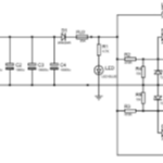
Como primera etapa se encuentra un transformador reductor, posteriormente se encuentra un puente rectificador de 160 A y una zona de filtrado por medio de capacitores encargados de la rectificación de onda completa; se agregó un diodo schottky cuya finalidad consiste en evitar que parte de la resonancia del circuito oscilador llegue a la parte de filtrado de capacitores, además se agregó un fusible de 20 A. Utilizando pulsos análogos como pulsos de disparo de los Mosfets, se genera una señal de alta frecuencia que alimenta el circuito tanque, compuesto por 10 capacitores de tipo MKPH, con una frecuencia de trabajo de 50kHz y una capacitancia de 0.33 uF, Anexo [A].
Por último, se encuentra la bobina de inducción, diseñada con una forma de tipo solenoide y construida con tubo de cobre de 0.93 cm de diámetro. Anexo [B].
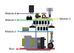
Modulo 1: Capacitores de alta frecuencia
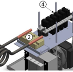
En esta etapa encontramos los elementos que sufren un aumento de temperatura, ya que es la etapa en la que la corriente eléctrica aumenta; este módulo recibe la refrigeración mediante aire forzado por medio de los ventiladores. Es este módulo en el que se encuentra la conexión de a bobina de inducción con el sistema eléctrico y el sistema de refrigeración líquida como se muestra en el Anexo [C].
En la siguiente tabla se enlistan los elementos existentes en el módulo 1.
| No. | Componente | Función |
| 1 | Bobina de inducción | Calienta por inducción metales ubicados en su interior |
| 2 | Soporte cerámico | Mantiene una conexión resistente a altas temperaturas y aísla eléctricamente las conexiones |
| 3 | Soporte de capacitores | Permite la conexión de varios capacitores en una base metálica |
| 4 | Banco de capacitores | Permite la carga y descarga de energía eléctrica de alta frecuencia |
Modulo 2: puente rectificador
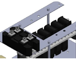
En este módulo encontramos la base que funciona como disipador de calor, mediante la refrigeración por aire forzado, como se observa en el Anexo [D].
Modulo 3: Circuito inversor resonante
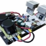
En este módulo se encuentra el circuito oscilador, Anexo [E], principal elemento para la generación de señales de alta frecuencia.
Este módulo requiere de una refrigeración forzada por aire y su disipador individual.
Modulo 4: Complemento de capacitadores rectificadores
En este módulo se encuentra u circuito compuesto por capacitores y un diodo, cuya finalidad es permitir el flujo de energía estable, evitando así la caída de voltaje debido al alto consumo en la inducción electromagnética. Anexo [F]
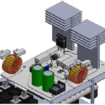
En el Anexo[G], se muestran los módulos que componen el sistema mecatrónico interno.
Resultados
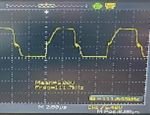
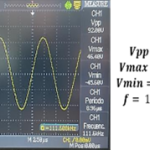
En el Anexo [H] se presenta un circuito inversor resonante ensamblado, cuyo funcionamiento fue analizado a través de un osciloscopio. En el Anexo [I] la señal de entrada al Mosfet Q1 es una onda semi cuadrada en forma de pulso, generada por la resonancia del circuito tanque. La señal para el Mosfet Q2 es similar, pero se activa cuando Q1 está apagado. Por otro lado, en el Anexo [J] la señal de salida de la bobina de inducción es senoidal, como se muestra en las mediciones con una sonda de 10X. El Anexo [K)] muestra que, al aplicar la señal de alta frecuencia, se creó un campo magnético variable en la bobina, lo que permitió observar el aumento de temperatura en piezas de metal ferromagnético. Finalmente, en el Anexo [L] se visualizó que los tornillos de metal alcanzaron temperaturas de 500°C en 5 minutos, y por lo tanto se observó un tubo de metal ferroso enrojecido a consecuencia de la inducción electromagnética.
Discusión
El resultado obtenido fue aceptable, siendo nuestra hipótesis aprobada, gracias a que el diseño y construcción del sistema mecatrónico presentó un funcionamiento acorde a lo requerido.
Conclusiones
El circuito inversor de corriente alterna genera 9.2 V, igual proporciona un amperaje de 48 A y una frecuencia de oscilación de 116.6 kHz las pruebas se realizaron a base de metal ferroso de 9.22 gramos, que requiere 48 A para alcanzar los 500°C. El tamaño del metal influye en qué tanta temperatura necesita, por ende, necesita mayor corriente eléctrica. Sin embargo, se tiene un riesgo de sobrecarga dando un aumento notable de temperatura en el transformador reductor y en los conductores eléctricos.
Por lo que se sugiere limitar la corriente de trabajo y las conexiones entre los subsistemas para evitar sobrecalentamientos y asegurar su funcionamiento.
Bibliografía
[1]S. Parra. Inducción Electromagnética: FARADAY, ciencia de alta tensión. España. National Geographic, 2012.
[2] A. Mercado, M. Martínez, F. Favila, A. García, “Historia Y Evolución De La Industria De Semiconductores Y La Integración De México En El Sector”, ESJ, Vol. 12, No. 18, pp. 65-78, Jun 2016
[3] J. L. Hernández, J. Sola y R. D. Fernández, “Estudio empírico de las corrientes de Foucault, combinando un campo magnético con el campo gravitatorio”, LAJPE, Vol. 13, No. 3, May-Ago, 2019.
[4] G. Mantilla, Instalaciones Eléctricas: La ley de Joule, Colombia. SENA, Modulo instruccional 8 Unidad 29. 1985.
[5] W. González, J. Aller, S. Laszlo y J. Hotvart, “Diseño y construcción de bobinas de calentamiento para hornos de inducción electromagnética”, UCT, Vol. 17, No. 66, pp. 28-37, marzo, 2013.
[6] W. S. Mejía y G. F. Villalobos, “Diseño de un horno por inducción para prácticas en laboratorio”, Proyecto integral de grado, FUA, Programa de ingeniería mecánica, Bogotá, Colombia, 2019.
NS- M- 29- LE Diseño y construcción de un inversor resonante para aplicaciones de calentamiento por inducción.
NS- M- 29- LE Diseño y construcción de un inversor resonante para aplicaciones de calentamiento por inducción.
Summary
This project consists on the design and assembly of a resonant inverter for its application in an induction heating system, through variable electromagnetic fields. The circuit is characterized by its self-switching, allowing the activation of a first Mosfet from which its respective quadrant will begin to charge its inductive elements and the resonant tank; subsequently it will be turned off by redirecting the current flow to the other quadrant.
The initial power supply comes from a transformer, which has the function of reducing the voltage to 16/32 allowing an amperage of up to 20 essential for inductive heating, while a rectifier bridge and a filtering system ensure a stable direct current; the resonant inverter circuit is a single-phase inverter responsible for transforming the DC current to a variable amplitude current with a frequency equal to or greater than the resonanci frequency RLC.Induction coils were constructed using copper pipes, utilizing equations for inductance calculation, as well as considering the equivalences of flux density and the toroid geometry. The output signal was recorded using an oscilloscope, showing a sine wave that indicates the correct functioning of the system. Experiments with ferromagnetic metal pieces demonstrated a temperature increase of up to 500°C, thus validating the functioning of the induction system.
Research Question
Is it possible to compress the design of an induction furnace without losing functionality when performing heat treatments on semiconductor materials?Problem approach
In industrial processes, machinery has evolved by using more technological methods to achieve or improve results that were previously obtained with older machines. As technology advances, new materials are developed to enhance systems from their electrical functioning. The use of mechatronic systems for material acquisition generates a constant benefit for the development of new technologies, among which the acquisition of semiconductors or alloys from a natural material can be highlighted. Depending on the material to be obtained, an analysis is necessary to select the systems that facilitate this acquisition. Commonly, for the acquisition of semiconductors, these are subjected to heat treatments using systems that allow the material’s temperature to be raised. Depending on the type of system used, different results can be obtained in the materials. Among the parameters that need to be altered are the temperature to which the sample will be exposed, the exposure time of the sample to that temperature, the cooling time, etc. Generally, resistive furnaces are used; however, a new option for supporting the acquisition of semiconductors is presented, which is the induction furnace. According to the capabilities of an induction furnace, it is expected to be of great support since it has a high-speed temperature increase and the stability of the temperature focused on a point of the sample will allow the generation of different heat treatments. The results will be complemented with the samples from resistive furnaces, so the difference or similarity in the reactions of the materials when exposed to a magnetic field that would generate their temperature increase or when exposed to the heat radiation of electric resistances will be observed.
Background
The acquisition of materials with different and specific properties according to their use, such as semiconductors, is achieved through heat treatments in high-temperature heating systems.
According to Y. Diaz in 2012, the use of an induction furnace allows the heating of metals, providing versatility by increasing the temperature without long waiting times for temperature rise and fall, as well as efficiency with high process performance and safety by not having gas emissions or other residues, dangerous electromagnetic radiation, or any other element that puts the user at risk. An aspect within thermal oxidation that can benefit it is the airflow inside the heating chamber where the sample is located, as mentioned by F. J. Hermenegildo in 2023, where a temperature of 500°C is used for 2 hours to expose the sample to that temperature, but what is added to the process is an airflow (already active before introducing the sample) of 600 sccm, benefiting the oxidation of the material exposed to the heat treatment.
Objective
Design and assemble an induction furnace from a resonant inverter circuit for its implementation in metal heat treatment processes through variable electromagnetic induction.
Justification
Over the years, advances in electrical systems have allowed the development of more compact and efficient circuits, making the use of semiconductor materials in their composition necessary, as these are essential in modern technology. Knowing their importance, various investigations have been carried out on the design and optimization of systems that allow the acquisition of semiconductors through heat treatments such as oxidation.
Although there are already established systems for obtaining semiconductors, it is also crucial to seek alternatives that present stable characteristics and minimize costs, offering the same or greater efficiency and performance in the processes carried out
Therefore, it is possible to adapt the operation of the induction heating system to obtain favorable results and achieve semiconductors, supported by the characteristics that this system offers, such as the temperature it can reach, as it has a high speed to reach its peak depending on the material exposed to the magnetic field. Additionally, the temperature does not decrease over time and does not aggressively wear out the components (burning them or altering their behavior), as long as the system has all the cooling measures determined in the design. This allows for both quick tests and prolonged time tests to observe any changes in the samples.
Hypothesis
Regarding the theory related to electromagnetic induction, it is possible to develop an induction furnace of smaller proportions compared to existing furnaces on the market, without compromising induction heating, as long as the necessary requirements to generate high frequency, heat-resistant components, and high electric current are met. According to the temperatures reached, it will be possible to subject material samples to obtain semiconductors through thermal oxidation.
Method (materials and procedure)
Electromagnetic Induction
It is a force that acts between magnets and magnetic materials. The physicist and chemist Faraday determined in his ELECTROMAGNETIC LAW that the variable magnetic field creates an electric field. The law states, ‘The induced voltage in a closed circuit is directly proportional to the rate of change over time of the magnetic flux passing through any surface with the circuit itself as the edge
Faraday said that a static magnetic field does not generate a current within a closed circuit, but when the same electric circuit is subjected to a time-varying magnetic field, it generates an electromotive force, which is expressed by the following equation
fem= -dφ/dt[V]
From this same law , it is implied a selenoid having:
fem= -N dφ/dt[V]
WHERE:
Fem= ELECTROMOTIVE FORCE
N = NUMBER OF TURNS
dφ= MAGNETIC FLUX DIFFERENTIAL
dt: TIME DIFFERENTIAL. [2]
Electromagnetic induction is the fundamental principle behind heating; however, it is important to note that the material’s behavior affects the process’s efficiency.
When heating a material, its magnetic properties change and are affected by hysteresis. This is important because hysteresis determines how the material responds to magnetization and demagnetization cycles, impacting the heating.
MAGNETIC HYSTERESIS
A property present in ferromagnetic materials is magnetic hysteresis when subjected to an external magnetic field. When a magnetic field H is applied, the material will reach a maximum level called saturation magnetization Ms with gradual magnetization. When the field is no longer applied, it will start to demagnetize without passing zero, as there remains a remanent magnetization Mr. Conversely, if another field is applied, it will obtain an inverse direction -M (saturating until reaching saturation) but with opposite polarization -Me.
This leads to a loop known as the hysteresis curve. Materials, when magnetized and demagnetized, produce energy losses and consequently an increase in the material’s temperature
That said, induction heating generates an alternating magnetic field that induces currents in a conductive material. As it varies, the material experiences magnetization and demagnetization cycles, causing hysteresis losses that, along with the Joule effect, generate heat
JOULE EFECT
Electric current generates heat within a conductor; this heating varies according to the current intensity, is proportional to the conductor’s resistance, and is proportional to the time the current passes through it. Based on the observed data, JOULE’S LAW was created, which expresses the amount of heat produced by an electric conductor through the following equation:
Q=0.24* I^2*R*t
BEING:
Q= HEAT IN CALORIES
I = INTENSITY IN AMPERES
R = RESISTANCE IN OHMS
0.24 = Constant (K)
t = TIME
It is understood that Joule’s Law helps us measure the amount of heat we are obtaining. At the same time, induced currents are generated in a material exposed to a variable magnetic field; the change in magnetic flux induces currents in the conductor, which also generate heat through the Joule effect
INDUCED CURRENTS
When a metal piece is subjected to a time-varying magnetic flux, eddy currents (induced) are generated. This produces a magnetic flux either by an electromagnet through an electromagnetic field via alternating current or when the center of a uniform magnetic field is displaced by direct current or magnets.
Energy losses increase squared in relation to the frequency of the alternating current, allowing, together with hysteresis, eddy currents, and the Joule effect, to generate an increase in temperature in ferromagnetic materials through induction.
INDUCTION HEATING
To generate induction heating, a considerable and time-varying electromagnetic field is generated. Through a circuit composed of a wire-shaped conductor and a source, an electric current can be generated to create this field. If the conductor wire is wound into a coil with multiple turns, the field can be intensified. [6]
After the electromagnetic field, a ferromagnetic piece is placed to take advantage of the power dissipation effect through the temperature increase produced by eddy currents. The magnetic field produces a hysteresis phenomenon that causes vibration and friction between the material’s molecules, known as the Joule effect.
Power dissipation through the temperature increase by the Joule effect occurs inside the piece influenced by the magnetic field where the induced currents have been created, making induction heating a method of heating materials without heat transfer from an external source. [7]
2.1 DESIGN:
Electrical design
Oscillator Circuit
The first stage is a step-down transformer, followed by a 160 A rectifier bridge and a filtering area through capacitors responsible for full-wave rectification. A Schottky diode was added to prevent part of the oscillator circuit’s resonance from reaching the capacitor filtering area, and a 20 A fuse was also added. Using analog pulses as trigger pulses for the MOSFETs, a high-frequency signal is generated to power the tank circuit, composed of 10 MKPH capacitors, with a working frequency of 50kHz and a capacitance of 0.33 uF, Annex [A].
Finally, there is the induction coil, designed in a solenoid shape and constructed with a copper tube of 0.93 cm in diameter, Annex [B].
Module 1: High-Frequency Capacitors
In this stage, we find the elements that experience a temperature increase, as it is the stage where the electric current increases; this module receives cooling through forced air via fans. This module contains the connection of the induction coil with the electrical system and the liquid cooling system, as shown in Annex [C].
The following table lists the elements present in module 1.
| No. | Component | Function |
| 1 | Induction coil | Heats metals located inside it by induction. |
| 2 | Ceramic support | It maintains a connection resistant to high temperatures and electrically insulates the connections |
| 3 | Capacitor support | Allows the connection of multiple capacitors on a metal bas |
| 4 | Capacitor bank | Allows the charging and discharging of high-frequency electrical energy |
Modulo 2: bridge rectifier
In this module, we find the base that functions as a heat sink through forced air cooling, as shown in Annex [D].
Modulo 3: Resonant inverter circuit
In this module, we find the oscillator circuit, Annex [E], the main element for generating high-frequency signals.
This module requires forced air cooling and its individual heat sink.
Module 4: Rectifier Capacitor Complement
In this module, there is a circuit composed of capacitors and a diode, whose purpose is to allow stable energy flow, thus avoiding voltage drops due to high consumption in electromagnetic induction. Annex [F]
In Annex [G], the modules that make up the internal mechatronic system are shown.
Results
In Annex [H], an assembled resonant inverter circuit is presented, whose operation was analyzed through an oscilloscope. In Annex [I], the input signal to the Mosfet Q1 is a semi-square wave in the form of a pulse, generated by the resonance of the tank circuit. The signal for the Mosfet Q2 is similar but activates when Q1 is off. On the other hand, in Annex [J], the output signal of the induction coil is sinusoidal, as shown in the measurements with a 10X probe. Annex [K] shows that, when applying the high-frequency signal, a variable magnetic field was created in the coil, allowing the observation of the temperature increase in ferromagnetic metal pieces. Finally, in Annex [L], it was observed that metal screws reached temperatures of 500°C in 5 minutes, and therefore a ferrous metal tube was seen to turn red due to electromagnetic induction.
Discussion
The result obtained was acceptable, and our hypothesis was approved, thanks to the fact that the design and construction of the mechatronic system presented an operation according to what was required.
Conclusions
The alternating current inverter circuit generates 9.2 V, also providing an amperage of 48 A and an oscillation frequency of 116.6 kHz. The tests were conducted on ferrous metal weighing 9.22 grams, which requires 48 A to reach 500°C. The size of the metal influences how much temperature is needed, thus requiring higher electric current. However, there is a risk of overload, causing a notable temperature increase in the step-down transformer and electrical conductors.
Therefore, it is suggested to limit the working current and the connections between subsystems to avoid overheating and ensure proper functioning.
Bibliography
[1] S. Parra. Electromagnetic Induction: FARADAY, high voltage science. Spain. National Geographic, 2012
[2] A. Mercado, M. Martínez, F. Favila, A. García, “History and Evolution of the Semiconductor Industry and Mexico’s Integration into the Sector”, ESJ, Vol. 12, No. 18, pp. 65-78, Jun 2016.
[3] J. L. Hernández, J. Sola, and R. D. Fernández, “Empirical study of eddy currents, combining a magnetic field with the gravitational field”, LAJPE, Vol. 13, No. 3, May-Aug, 2019.
[4] G. Mantilla, Electrical Installations: Joule’s Law, Colombia. SENA, Instructional Module 8 Unit 29. 1985..
[5] W. González, J. Aller, S. Laszlo, and J. Hotvart, “Design and construction of heating coils for electromagnetic induction furnaces”, UCT, Vol. 17, No. 66, pp. 28-37, March, 2013.
[6] W. S. Mejía and G. F. Villalobos, “Design of an induction furnace for laboratory practices”, Comprehensive degree project, FUA, Mechanical Engineering Program, Bogotá, Colombia, 2019


